一、GPIO简介
·GPIO(General Purpose Input Output)通用输入输出口
·输出模式下:可控制端口输出高低电平,用以驱动LED、控制蜂鸣器、模拟通信协议输出时序等
·输入模式下:可读取端口的高低电平或电压,用于读取按键输入、外界模块电平信号输入、ADC电压采集、模拟通信协议接收数据等
二、GPIO结构

三、GPIO位结构
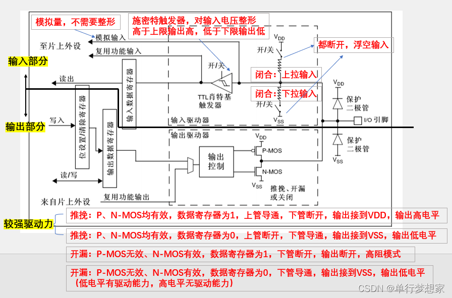
四、GPIO模式

4.1 浮空/上拉/下拉输入
(GPIO_Mode_IN_FLOATING/GPIO_Mode_IPU/GPIO_Mode_IPD)

4.2 模拟输入(GPIO_Mode_AIN)
 4.3 开漏/推挽输出
(GPIO_Mode_Out_OD/GPIO_Mode_Out_PP)

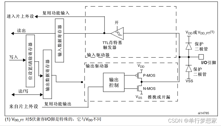
4.4 复用开漏/推挽输出
(GPIO_Mode_AF_OD/GPIO_Mode_AF_PP)
五、GPIO库函数
void GPIO_DeInit(GPIO_TypeDef* GPIOx);//复位GPIO外设
void GPIO_Init(GPIO_TypeDef* GPIOx, GPIO_InitTypeDef* GPIO_InitStruct);//初始化GPIO
void GPIO_StructInit(GPIO_InitTypeDef* GPIO_InitStruct);//给结构体赋默认值GPIO读取函数
uint8_t GPIO_ReadInputDataBit(GPIO_TypeDef* GPIOx, uint16_t GPIO_Pin);//读取输入数据寄存器某一个端口的输入值
uint16_t GPIO_ReadInputData(GPIO_TypeDef* GPIOx);//读取整个输入数据寄存器,返回一个16位的数据
uint8_t GPIO_ReadOutputDataBit(GPIO_TypeDef* GPIOx, uint16_t GPIO_Pin);//读取输出数据寄存器某一个端口的输入值(输出模式)
uint16_t GPIO_ReadOutputData(GPIO_TypeDef* GPIOx);//读取整个输出数据寄存器
GPIO写入函数
void GPIO_SetBits(GPIO_TypeDef* GPIOx, uint16_t GPIO_Pin);//设置高电平
void GPIO_ResetBits(GPIO_TypeDef* GPIOx, uint16_t GPIO_Pin);//设置低电平
void GPIO_WriteBit(GPIO_TypeDef* GPIOx, uint16_t GPIO_Pin, BitAction BitVal);
void GPIO_Write(GPIO_TypeDef* GPIOx, uint16_t PortVal);void GPIO_PinLockConfig(GPIO_TypeDef* GPIOx, uint16_t GPIO_Pin);
六、实验(GPIO输出)
6.1 LED闪烁
#include "stm32f10x.h"                  // Device header
#include "Delay.h"

int main(void)
{
	//一、使用RCC开启GPIO时钟
	RCC_APB2PeriphClockCmd(RCC_APB2Periph_GPIOA,ENABLE);

	//二、使用GPIO_Init函数初始化GPIO
	GPIO_InitTypeDef GPIO_InitStructure;
	GPIO_InitStructure.GPIO_Mode = GPIO_Mode_Out_PP;
	GPIO_InitStructure.GPIO_Pin = GPIO_Pin_1;
	GPIO_InitStructure.GPIO_Speed = GPIO_Speed_50MHz;
	GPIO_Init(GPIOA,&GPIO_InitStructure);


	while (1)
	{
		//=====one:GPIO_WriteBit=====//
//		GPIO_WriteBit(GPIOA,GPIO_Pin_0,Bit_RESET);
//		Delay_ms(500);
//		GPIO_WriteBit(GPIOA,GPIO_Pin_0,Bit_SET);
//		Delay_ms(500);

		//=====two:GPIO_WriteBit 0/1=====//
//		GPIO_WriteBit(GPIOA,GPIO_Pin_0,(BitAction)0);
//		Delay_ms(500);
//		GPIO_WriteBit(GPIOA,GPIO_Pin_0,(BitAction)1);
//		Delay_ms(500);

		//=====three:GPIO_ResetBits  GPIO_SetBits=====//
		GPIO_ResetBits(GPIOA,GPIO_Pin_0);
		Delay_ms(500);
		GPIO_SetBits(GPIOA,GPIO_Pin_0);
		Delay_ms(500);

	}
}
6.2 LED流水灯
#include "stm32f10x.h"                  // Device header
#include "Delay.h"

int main(void)
{
	RCC_APB2PeriphClockCmd(RCC_APB2Periph_GPIOA,ENABLE);

	GPIO_InitTypeDef GPIO_InitStructure;
	GPIO_InitStructure.GPIO_Mode = GPIO_Mode_Out_PP;
	GPIO_InitStructure.GPIO_Pin = GPIO_Pin_0 | GPIO_Pin_1 | GPIO_Pin_2 | GPIO_Pin_3 | GPIO_Pin_4 | GPIO_Pin_5 | GPIO_Pin_6 | GPIO_Pin_7;
	//GPIO_InitStructure.GPIO_Pin = GPIO_Pin_All;
	GPIO_InitStructure.GPIO_Speed = GPIO_Speed_50MHz;
	GPIO_Init(GPIOA,&GPIO_InitStructure);


	while (1)
	{
		GPIO_Write(GPIOA,~0x0001);//0000 0000 0000 0001,PA15-PA0,低电平驱动所以取反
		Delay_ms(100);
		GPIO_Write(GPIOA,~0x0002);//0000 0000 0000 0010
		Delay_ms(100);
		GPIO_Write(GPIOA,~0x0004);//0000 0000 0000 0100
		Delay_ms(100);
		GPIO_Write(GPIOA,~0x0008);//0000 0000 0000 1000
		Delay_ms(100);
		GPIO_Write(GPIOA,~0x0010);//0000 0000 0001 0000
		Delay_ms(100);
		GPIO_Write(GPIOA,~0x0020);//0000 0000 0010 0000
		Delay_ms(100);
		GPIO_Write(GPIOA,~0x0040);//0000 0000 0100 0000
		Delay_ms(100);
		GPIO_Write(GPIOA,~0x0080);//0000 0000 1000 0000
		Delay_ms(100);
	}
}
6.3 蜂鸣器
#include "stm32f10x.h"                  // Device header
#include "Delay.h"

int main(void)
{
	RCC_APB2PeriphClockCmd(RCC_APB2Periph_GPIOB,ENABLE);

	GPIO_InitTypeDef GPIO_InitStructure;
	GPIO_InitStructure.GPIO_Mode = GPIO_Mode_Out_PP;
	GPIO_InitStructure.GPIO_Pin = GPIO_Pin_12;
	GPIO_InitStructure.GPIO_Speed = GPIO_Speed_50MHz;
	GPIO_Init(GPIOB,&GPIO_InitStructure);


	while (1)
	{
		GPIO_ResetBits(GPIOB,GPIO_Pin_12);
		Delay_ms(500);
		GPIO_SetBits(GPIOB,GPIO_Pin_12);
		Delay_ms(500);
	}
}
七、实验(GPIO输入)
7.1 按键控制LED
main.c
#include "stm32f10x.h"                  // Device header
#include "Delay.h"
#include "LED.h"
#include "key.h"

uint8_t KeyNum;

int main(void)
{
	LED_Init();//LED初始化
	Key_Init();//按键初始化

	while (1)
	{
		KeyNum = Key_GetNum();//判断是哪一个按键按下
		if(KeyNum == 1)
		{
			LED1_Turn();
		}
		if(KeyNum == 2)
		{
			LED2_Turn();
		}
	}
}
LED.c
#include "stm32f10x.h" // Device header void LED_Init(void) { RCC_APB2PeriphClockCmd(RCC_APB2Periph_GPIOA,ENABLE); GPIO_InitTypeDef GPIO_InitStructure; GPIO_InitStructure.GPIO_Mode = GPIO_Mode_Out_PP; GPIO_InitStructure.GPIO_Pin = GPIO_Pin_1 | GPIO_Pin_2; GPIO_InitStructure.GPIO_Speed = GPIO_Speed_50MHz; GPIO_Init(GPIOA,&GPIO_InitStructure); GPIO_SetBits(GPIOA,GPIO_Pin_1 | GPIO_Pin_2);//初始化高电平 } //=====LED1=====// void LED1_ON(void) { GPIO_ResetBits(GPIOA,GPIO_Pin_1); } void LED1_OFF(void) { GPIO_SetBits(GPIOA,GPIO_Pin_1); } void LED1_Turn(void) { if(GPIO_ReadOutputDataBit(GPIOA,GPIO_Pin_1) == 0) //读取LED输出的高低电平,控制翻转 { GPIO_SetBits(GPIOA,GPIO_Pin_1); } else { GPIO_ResetBits(GPIOA,GPIO_Pin_1); } } //=====LED2=====// void LED2_ON(void) { GPIO_ResetBits(GPIOA,GPIO_Pin_2); } void LED2_OFF(void) { GPIO_SetBits(GPIOA,GPIO_Pin_2); } void LED2_Turn(void) { if(GPIO_ReadOutputDataBit(GPIOA,GPIO_Pin_2) == 0) { GPIO_SetBits(GPIOA,GPIO_Pin_2); } else { GPIO_ResetBits(GPIOA,GPIO_Pin_2); } }key.c
#include "stm32f10x.h"                  // Device header
#include "Delay.h"

//===按键初始化===//
void Key_Init(void)
{
	RCC_APB2PeriphClockCmd(RCC_APB2Periph_GPIOB,ENABLE);

	GPIO_InitTypeDef GPIO_InitStructure;
	GPIO_InitStructure.GPIO_Mode = GPIO_Mode_IPU;//上拉输入
	GPIO_InitStructure.GPIO_Pin = GPIO_Pin_14 | GPIO_Pin_11;
	GPIO_InitStructure.GPIO_Speed = GPIO_Speed_50MHz;
	GPIO_Init(GPIOB,&GPIO_InitStructure);
}

//===获取按键返回码===//
uint8_t Key_GetNum(void)
{
	uint8_t KeyNum = 0;
	if(GPIO_ReadInputDataBit(GPIOB,GPIO_Pin_14) == 0)
	{
		Delay_ms(20);//消抖
		while(GPIO_ReadInputDataBit(GPIOB,GPIO_Pin_14) == 0);//如果不松手则卡着
		Delay_ms(20);
		KeyNum = 1;
	}
	if(GPIO_ReadInputDataBit(GPIOB,GPIO_Pin_11) == 0)
	{
		Delay_ms(20);//消抖
		while(GPIO_ReadInputDataBit(GPIOB,GPIO_Pin_11) == 0);
		Delay_ms(20);
		KeyNum = 2;
	}
	return KeyNum;
}
7.2 光敏传感器控制蜂鸣器
main.c
#include "stm32f10x.h"                  // Device header
#include "Delay.h"
#include "Buzzer.h"
#include "LightSensor.h"

int main(void)
{
	Buzzer_Init();//蜂鸣器初始化
	LightSensor_Init();//光敏传感器初始化

	while (1)
	{
		if(LightSensor_Get() == 1){
			Buzzer_ON();
		}
		else{
			Buzzer_OFF();
		}
	}
}
Buzzer.c
#include "stm32f10x.h" // Device header //===蜂鸣器初始化===// void Buzzer_Init(void) { RCC_APB2PeriphClockCmd(RCC_APB2Periph_GPIOB,ENABLE); GPIO_InitTypeDef GPIO_InitStructure; GPIO_InitStructure.GPIO_Mode = GPIO_Mode_Out_PP; GPIO_InitStructure.GPIO_Pin = GPIO_Pin_12; GPIO_InitStructure.GPIO_Speed = GPIO_Speed_50MHz; GPIO_Init(GPIOB,&GPIO_InitStructure); GPIO_SetBits(GPIOB,GPIO_Pin_12);//初始化高电平 } void Buzzer_ON(void) { GPIO_ResetBits(GPIOB,GPIO_Pin_12); } void Buzzer_OFF(void) { GPIO_SetBits(GPIOB,GPIO_Pin_12); } void Buzzer_Turn(void) { if(GPIO_ReadOutputDataBit(GPIOB,GPIO_Pin_12) == 0) //读取蜂鸣器输出的高低电平,控制翻转 { GPIO_SetBits(GPIOB,GPIO_Pin_12); } else { GPIO_ResetBits(GPIOB,GPIO_Pin_12); } }#include "stm32f10x.h" // Device header //===光敏传感器初始化===// void LightSensor_Init(void) { RCC_APB2PeriphClockCmd(RCC_APB2Periph_GPIOB,ENABLE); GPIO_InitTypeDef GPIO_InitStructure; GPIO_InitStructure.GPIO_Mode = GPIO_Mode_IPU;//上拉输入 GPIO_InitStructure.GPIO_Pin = GPIO_Pin_13; GPIO_InitStructure.GPIO_Speed = GPIO_Speed_50MHz; GPIO_Init(GPIOB,&GPIO_InitStructure); } //===获取返回码===// uint8_t LightSensor_Get(void) { return GPIO_ReadInputDataBit(GPIOB,GPIO_Pin_13); }
八、总结
原文地址:https://blog.csdn.net/qq_52902991/article/details/134755567
本文来自互联网用户投稿,该文观点仅代表作者本人,不代表本站立场。本站仅提供信息存储空间服务,不拥有所有权,不承担相关法律责任。
如若转载,请注明出处:http://www.7code.cn/show_48724.html
如若内容造成侵权/违法违规/事实不符,请联系代码007邮箱:suwngjj01@126.com进行投诉反馈,一经查实,立即删除!